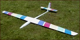
WING CONSTRUCTION FOR VACUUM BAGGING by Graham Woods |
||
 CONSIDERATIONS CONSIDERATIONSThe idea of wing bagging is to lay-up fibre glass and or carbon fibre or Kevlar™ on painted shiny plastic sheet with epoxy resin and then transfer this skin to extruded foam wing cores using a vacuum bag. With a model that has 4 servos in the wings like my Rumour:aerobatic here I think you will need to add a spar while smaller model (< 2.4m) with only 2 servos may not need a spar. The choice is yours. The plastic sheet used for the lay-up is often 14 mil polyester Mylar™ which has an exceptional surface finish. I personally use cheaper PVC sheet. The thickness I choose is stiff enough to 'carry over' any minor imperfections in the wing surface but will still go over the curve of the wing surface easily. It is 0.48mm thick or 19 mil (0.019"). For lay-up I like to use a fibreglass surface 'veil' cloth of 25 or 40 gsm (~ 1 oz/sq.yd) to help mask any weave pattern showing on the wing surface from subsequent lower layers of cloth. For the main body of my wings I like to use 100 gsm carbon fibre cloth cut at 45º bias. It is very expensive! As a cheaper alternative you can use 200 gsm carbon fibre cloth. If you only want to use glass then equivalent plies of 200-300 gsm should suffice. To prepare the PVC sheet I use a proprietary glass cleaner and then apply a wipe of Freekote™ release agent. With Mylar™ this should not be necessary. I spray using car aerosol paint (light coats to prevent 'fish-eyes'). For my vacuum bags I use polythene lay-flat tubing rather than the regular nylon bagging material and seal it with vac bag caulking off the roll. (You can use double sided Scotch tape or packing tape to seal bags too.) I cut all my pieces of cloth before mixing any resin. I first spray the PVC with light coats of white primer paint and leave to dry for a couple of hours. I then lay-up the first veil layer of cloth. I spread resin with an old credit card. Leave for 3 hours for the resin to gel or 'go green'. I then lay up the carbon fibre using a new mix of resin. I vacuum one side of a wing at a time although I have done both sides together.
|
||
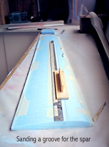
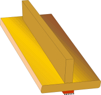 SANDING BLOCK SANDING BLOCKI find creating a groove in foam cores for a spar is easily achieved with a purpose made sanding block. Make it from any scrap materials you have to hand - most modellers have small pieces of balsa, foam and plywood laying around. Make up a block similar to the one in my illustration here on the left. The idea is that you gently sand a groove in the foam wing core up against a straight edge until the base of the sanding block rests on the surface of the foam. |
||
Do use the foam beds to work on the foam core this will limit the damage that can occur. START off gently on the top surface against the straight edge, then remove it and in just a few minutes you will have a nice channel for a spar. Using this method an even depth and width of groove is achieved and your carbon tows should lie flat and make an even surface. You need to use a fine grit oxide paper to give a smooth surface to the groove and to make sure you don't go pulling chunks of foam from it. Tape the core in place with paper masking tape, hold the straight edge in place too. Where should you put the spar? Good question. Remember that servos and servo wires have to go in. |
||
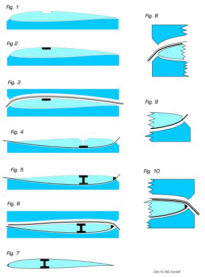
 CORE PREPARATION CORE PREPARATIONWhen you cut your cores make sure you have extra foam at the leading and trailing edges. Your first task is to chamfer the edge of the blue foam at a suitable angle at the leading edge so that the Mylar or Plastic sheet (I use 0.48mm PVC) can more or less follow the contour of the leading edge (Fig. 1 in diagram 2). Tape over the inner area and sides of the foam beds with brown packing tape to prevent anything sticking to the beds. |
||
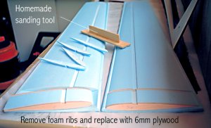
ROOT RIBS After I have cut my wing cores I slice off four ¼ inch foam ribs: two from the roots of the wing panels and two from about 2 inches in from the root. See above. The intention is to replace these foam ribs with ones made from plywood. Two inches is entirely adequate - there's no need for it to be more. With these foam ribs cut out it's not much of a problem to carefully trace round them on to plywood and then cut the ply replacement ribs out using a bandsaw. Getting them accurate is of course something else! If anything, I err on the side of cutting very, very slightly undersize assuming that bagging is going to crush the foam to some extent. For a wing from 2 - 3 meter span I would use ¼ inch ply (quality birch ply not that poor quality reddish coloured type nor lite-ply). |
||
With the four perfect ply ribs I have cut the next step is to drill them all together to take the brass wing dowel tubes. (I have moulded my own carbon fibre joiners in the past but prefer to use steel.) For an aerobatics model of around 2½ metres I would use a pair of ¼ inch diameter K & S steel dowels and the brass tube that fits it (~9/16" ); a smaller diameter for a smaller wing, of course. If your model has a round fuselage without wing fairings now is a good time to duplicate and drill the wing root ribs to create wing fairings for your fuselage sides at a later date. In this way all dowels and ribs are in perfect alignment. I glue the ply ribs to the foam pieces with 5 minute epoxy resin including a sheet of card (not glued) between the two 'root' root ribs. Now I remove the foam from around where the wing dowel tubes will go and replace that foam with, say, ½ inch vertical grain balsa - this will provide extra support for the dowel tubes in the event the wings should pop-out during flight. See diagram 1 below I glue the balsa in place in the foam with epoxy. BEFORE trimming off the excess protruding balsa I drill out the holes for the wing dowel tubes. If you do this step the other way round it's likely that your drill bit will tear through the balsa surface. |
||
DIAGRAM 1 |
||
|
||
| Make sure you cut the steel wing dowels
pass through both ply ribs and that the brass tube
doesn't support the steel joiners alone! |
||
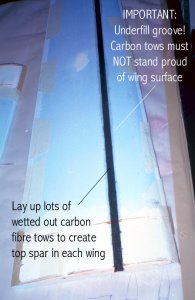
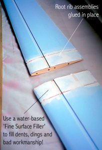 READY TO GET MESSY READY TO GET MESSYWith all this work on the foam wing roots it's quite possible that you have nicked and dented the foam; I fill damaged foam with something called Fine Surface Polyfilla (a water based plaster filler) in the UK. When all this work is done the last step is to glue the wing root assemblies back to the wing cores using the foam beds as guides. The wing panels are now ready for bagging and of course the wing dowels line up perfectly! The next thing to do is to cut all your carbon tows to the correct length before you even go near your epoxy resin. But how many tows? I hear you say. Since I buy my 40k tows in 1kg rolls I also get the manufacturers info and it says it has a cross-sectional area of 1.47mm². Let's imagine a spar 3mm deep and 12mm wide then simple math tells me that I need 24 tows of 40k without taking account of the volume of epoxy resin. Using this method the best ratio of fibre to resin is about 40/60 so this reduces the number of 40k tows to ~10 for such a spar cap. |
||
Armed with your pre-cut tows, mix up your resin and wet out the tows. I find the easiest way to do this is by hand with a rubber glove (all the usual warnings here - gloves, barrier cream, clean working, no eating, drinking or smoking!). Warming the resin with a heat gun reduces its viscosity too but watch out here - too hot and the fumes are VERY dangerous!!! Wet the groove with resin and then fill up the groove in the foam with tows but do not overfill the groove - there must be NO CARBON STANDING PROUD of the foam surface. This is why it is important to use a sanding block to get an even depth groove. With the groove underfilled slightly leave the resin to harden. The resulting underfill can now be filled with a stiff mixture of resin and microballoons (or soft spackle), left to harden and sanded off remembering to mask off the surrounding foam so that you do not damage the foam around the spar cap. (Fig. 2 in diagram 2) |
||
Place the wing core, prepared earlier by covering with brown packing tape, on the lower bed and align the wetted skin/plastic sheet very accurately on the wing core (Fig. 3 in diagram 2) Now put the lower bed and core in the vacuum bag together, the upper foam bed goes OUTSIDE the bag. Apply your vacuum. I use 0.48mm (0.0019") sheet because I find it is stiff enough not to go into every imperfection and dent on the foam yet stiff enough to go over the curve of the wing surface. As for the amount of vacuum to apply, this depends on the foam. I find that with blue foam about half a vacuum (½ Bar or 7 psi) is adequate, perhaps a little more, before the foam starts to be crushed. |
||
Removing the plastic sheet from a bagged wing is always a time of pleasure and apprehension - it should come off easily and in one go. If it doesn't, then something's gone wrong somewhere. With our wing now with one skin on the upper surface the next step is to sand the second spar cap groove in the lower surface of the wing using your home-made sanding block and then cutting a slot for the shear web. (Figs. 4 & 5 in diagram 2) The slot is done first with a blade along a straight edge until you can feel the carbon spar cap of the top surface under the knife. Widen this cut with a saw blade - it could be a hacksaw, wood saw or razor saw - it just needs to take out a slot of the correct size for the shear web which is just slid in place with resin when you fill the second spar cap. (I make shear webs of either plywood or more commonly 2 plies of 200gsm carbon cloth laid up with resin between two sheets of plastic.) |
||
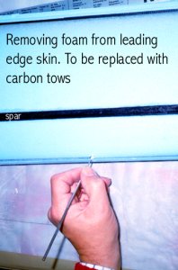 LEADING EDGE LEADING EDGEWhile we're here it's also time to do the leading edge. From Fig. 4 in diagram below I hope you can see that I remove a slither of foam from the leading edge and simply replace it with carbon fibre tows, like the spar. Hopefully, the upper leading edge should be quite accurate, underfill the leading edge and spar with carbon tows once again, leave to harden and fill the underfill with a stiff epoxy/microballoon spackle and finally sand it to shape trimming off the excess upper skin. (Figs. 5 & 9, diagram 2) A WORD ON CLOTH My personal preference is always to use carbon fibre cloth. I have used 200 gsm (~6oz/sq.yd) in the past but now favour 100 gsm carbon plain weave (~3oz/sq.yd) laid at 45º bias for my lay-up. This together with a veil-cloth (for the very outside surface of the wing) of 25 or 40 gsm (~1oz/sq.yd) glass gives a torsionally stiff wing. |
||
I hate putting in the wires and servos. Here I used Multiplex servos and their servo cans and shrouds. You may think that my wing doesn't look too good in this picture - here's the reason. When I spray the plastic sheet before lay-up I use white primer matt car aerosol paint. It doesn't dry to a gloss but does give me a base for future painting. After all, there's no point in having a perfect finish and then setting about ruining it when you install servos, wires, horns, hinges. My wings get their top coat after wards. |
||
Well here are my wings almost finished. The wires need plugs on them. I hinged the wings using silicone bathroom caulking, the one that smells of vinegar, but that's another story. You may notice that there are extra wires hanging out from the wing roots. When I made the wings I incorporated wires to the wing tip for smoke canisters. I made my tailplane in much the same way and the rudder too. Both are carbon skinned blue foam. The bellcrank for the tailplane was made from fibre glass PCB. |
||
DIAGRAM 2 ..........Bagging Step by Step |
||
|
Copyright © 1999 - 2001 Graham Woods Please ask permission for use, it is nearly always granted. |
 SANDING A GROOVE
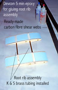 ROOT RIB ASSEMBLY
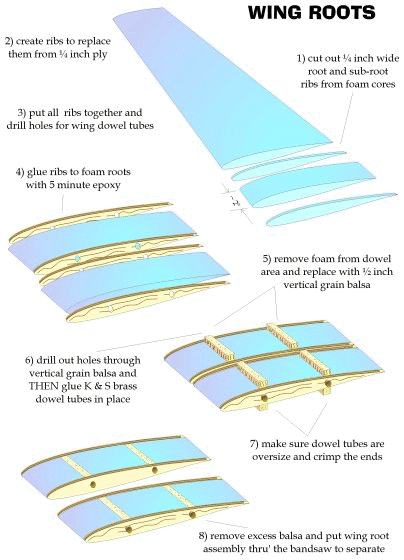
 LAY-UP
 FIRST BAGGING
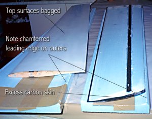 2nd SPAR AND LEADING EDGE
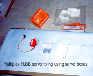 SERVOS
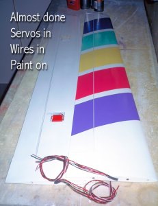 FINISHING