MORE VACUUM TECHNIQUES by Graham Woods |
|
 RUDDER HINGE RUDDER HINGEBefore you bag your rudder foam core, slice off its leading edge and file a groove in both pieces of the foam to take a length of aluminium tube or plastic snake outer. Start by cutting the groove with a knife blade then use a needle file to open it out if you can but I found an easy alternative. Get the piano wire which you will use for the rudder hinge and fold around it a piece of very fine sandpaper so that you effectively have a U-shaped piece of grit paper and sand away slowly and gently. Enclose the tube in the rudder and glue it all together with epoxy resin - a five minute resin will do. Face the ends of the rudder with scrap wing skin or 1/64" ply. Now bag your rudder in your usual way. A small piece of sticky tape over the open ends of the tube (or even plugging the tube ends with soft balsa) will prevent epoxy from finding its way inside! You don’t need that sort of hassle with a beautifully formed rudder! Next pay attention to your rudder post. Get it to fit to the fuselage fin but don’t glue it yet. You need to cut some little hinge points from glass fibre printed circuit board (PCB). They need to be drilled to take the piano wire. Cut slots in the rudder post to take these hinge points. Watch out here you may snap your rudder post if you’re not careful! I know, I’ve done it. Offer up the rudder post to the now bagged rudder and mark the hinge points on the rudder. Cut slots for these hinge points (cut through the enclosed tube too) - a junior hacksaw (or fine-toothed bandsaw/jigsaw) will do the job easily. If you need to widen the slot a little, use a flat needle file. Fit the rudder to the rudder post temporarily to make sure the movement is OK. Disassemble all the pieces and glue the hinge points into the rudder post with epoxy resin. (If you want to be really smart you can, of course, ‘pin’ the hinge points too on the rear of the post using small pieces of cocktail stick pushed through a second drilled hole in the PCB hinge points.) Finally, remove the rudder and fit the rudder post. I generally make my rudder posts out of plywood (say, 1/8"), sometimes home-made Nomex/carbon sheet, and fit them in with a slow epoxy. I also add tows of carbon fibre too on each side of the rudder post to stiffen up the fuselage fin even more. It needs to follow the contour of the leading edge of the rudder after all and carbon tows slide into the corners with ease. The beauty of this method is that if you get the thickness of your rudder and depth of the rudder post in the fuse correct, then the leading edge of the rudder is shrouded to some extent by the glass sides of the fuse fin. No unsightly gaps here then! One added advantage is that the rudder can actually be removed if needs be. I like my slope planes to be rugged and this type of home-made rudder hinge with nylon covered fishing trace wires for ‘pull-pull’ rudder operation has worked very well for me over the years. |
|
 RIGID PIVOT RIGID PIVOTI hate wobbly tailplanes! I've seen them sitting there in the model pound, in the wind, flapping about. What are people thinking of? I reckon every part of my models should be as rigid as possible; here then is the solution I use to make rigid stabs for my slope soarers. You need to find a length of aluminium rod (or steel) about one centimetre (cm) in diameter (~0.4 inches). I have such a length of rod and I slice off a piece exactly the width of the fuselage fin, where the main tailplane dowel goes, each time I make a new model. I know its quite heavy but I reckon that's a small price to pay for a stab pivot that never comes un-glued and gets the wobbles. That's the easy bit, next you need to drill a hole through the centre of it, that's the difficult bit! So you need to have a pillar drill, or struggle like I do. Without one, it's hard to get the hole concentric. The hole should be as close a fit as possible to the diameter of the tailplane dowel - smart guys might even drill the hole slightly smaller and heat the drilled pivot to get a really tight fit; add a drop of cynaoacrylate adhesive to fix it, otherwise use epoxy resin. I'm afraid you can't use a regular store bought bellcrank for this style of pivot - you have to make your own. I find glassfibre printed circuit board (PCB) is ideal. It needs to be drilled/rasped out to take the whole 1 centimetre diameter pivot piece. While you're taking the edge off that new saw blade cutting the crank, cut a pair of 'washers' from PCB too. (Glass PCB is one of the best materials for blunting blades, BTW.) These washers are for the inside of the fuselage sides to provide extra support for the pivot. Dry fit all the parts to make sure you haven't done anything stupid. Mark on the fuse sides the curve of the second stab rod by simply inserting a pencil in it's hole in the crank and rotating it to make a mark on the fuse sides. Cut the slots for the rear dowel rod in the fuse now before gluing the pivot in place. Roughen up all the parts that are going to take the slow cure epoxy resin with a coarse rasp and then fix the pivot and crank in place. Easier said than done, eh? True, the resin can get in the crank pivot so you have to be careful. I found that having a small paintbrush and acetone ready at hand will help to ease the crank on the pivot should you get any resin get in there, which is quite likely. :-) |
|
 TAILPLANE JOINERS TAILPLANE JOINERSIn my quest for an ALL composite plane I had to devise some method for the tailplane joiners. They had to be light and durable and easy to make. I looked around the workshop and came up with the idea of using a paste made of microballoons and epoxy resin. I decided to embed the stab joiner tubes in this mix; but how to do it? Well, I've ended up with a box of those square rubber grommets for servo fixing which come as spares and I use these. I cut my aluminium dowel tubes over length and slip a grommet over each to support my dowel 'in mid-air' so to speak. Next, I make a small frame from scrap balsa and fill the volume around the tubes with a nice, stiff, easily sandable mixture of microballoons and resin. When the resin has cured I remove the balsa frame by snapping it away from the hardened resin mix and set to work with sandpaper to get it into shape and trim off the rubber grommets. I join my stab halves with 5 minute resin (the merest hint of adhesive I might say) and cut slots for the stab joiners I just made. I then bag the whole elevator between PVC sheets. I put my elevator through the band saw when the tailplane is cured. That way the two halves fit perfectly. |
|
 |
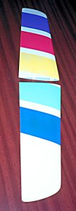 |
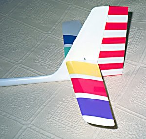
The finished fin, rudder and tailplane of the STORM as described here. Copyright © 1999 - 2001 Graham Woods Please ask permission for use it is nearly always granted. |
|