|
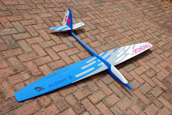
THE ARESTI 2M |
|||||||||||||||||||||
already have the best aerobatic slope soarer I have ever had, the Kinetic. The latest iteration of this design is now called Raptor and will be offered by Baudismodel.com in the Czech Republic if the demand is there. This firm make the Jedi and Pitbull and are renowned for the quality of their mouldings. Mind you, the airframe costs €1100/1390 plus six very expensive servos (~£75) designed to fit exactly in the model, making it a snip at somewhere near a mere £1500 ready to fly. EUROPE vs ASIA A cheaper alternative, or dare I say rival, is the Aresti 2M from Jim Hammond over in Taiwan; this one costs about €650 so still a pricey thing for all the dedicated few. The main difference in price is due to the cost of labour I imagine; one assumes that wages in Europe are more than the Far East and this cost is also reflected in the quality of the finished model too. I'm sorry to say that models from the Aeroic & RCRCM stables are apt to spring apart (IMHO) upon a heavy landing or crash. (i.e. Minivec, Aresti, Stormbird etc.) I mean to say that inspection after a mishap can reveal that a seam or joint supposed to be held together by a resin/microballoon paste may not be in physical contact with all the parts it is supposed to be gluing together. While the outside finish is often very, very good the insides, then, may have shortcomings. Even so, I can repair models and I nevertheless bought an Aresti 2M. |
 |
||||||||||||||||||||
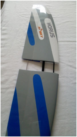
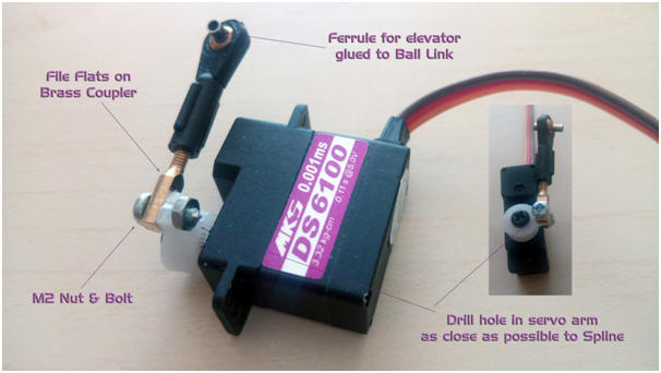
What is different about this model is the stabiliser, it is fixed to the fuselage with two carbon rods and has a moving elevator driven by a direct linkage. While the fibreglass servo tray is pre-cut for an elevator and rudder servo, provision has been made for a direct drive servo at the base of the fin. You have to make this linkage yourself, no bits were supplied in my 'kit', see my image. A fixed tailplane removes the wobble that one always gets with AMTs and it should ensure that you get the CG correct if you don't want to fly around with 'up' elevator showing in the cruise position. A direct linkage should remove any slop one may encounter with the in-built 'snake-in-tube' pushrods for the elevator and rudder. However, while this set up gives a rigid elevator, after a time the top hinge of the elevator at the fin on this model, a strip of Kevlar, does begin to become detached from the upper skin of the stabiliser at the root. While the servo pulls against the hinge for 'down-elevator', it pushes the elevator away from the Kevlar hinge with 'up-elevator'. A piece of tape, like Blenderm, can help alleviate the weakness here, or even a sliver of Mylar hinge slipped under the skin would help stiffen up the elevator when it loosens. A solution tried by Stuart Grey, which seems to work, is to do away with a 'tired' stab/elevator top hinge combination by gluing or taping together the elevator and stab, and removing the front carbon dowel and using the now joined stab/elevator as an all moving tailplane rotating on the main dowel. The elevator servo is very vulnerable in the fin, a heavy landing and it can come lose very easily I'm told. Instructions say to glue it in position with 5 min. epoxy but as you know a sharp knock and epoxy can easily detach itself. This is how one removes the servo if needs be. I supported the servo to an extent with some pieces of ply inside the fin but you may see people replace the supplied servo cover with a clear piece of plastic salvaged from a bubble pack or similar. This means they can see if the servo has come loose. A strip of PCB or scrap carbon sheet also serves to hold the servo in place. |
|||||||||||||||||||||
 |
 |
||||||||||||||||||||
|
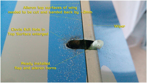
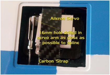
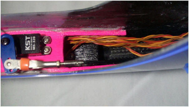
If I thought the elevator servo installation was awkward I can say that I struggled even more with the wing servos. First, I had to cut back the top surface of the wing at the aileron to get the maximum up-movement I could get. I was using KST135 MG servos with a torque of ~4kg.cm and while these are very strong for a wing they can only push so far against a stiff linkage. Nicer to have an easy non-servo-stalling movement. Cutting through the pristine, painted carbon top skin is a delicate business lest one slips with the blade. I was fearful of damaging the Kevlar hinge (some moulders use Peel Ply, btw) working on the cut, folding the surface up and down, and then the subsequent hacking of the wing skins I had to do where the clevises exit the wings. I finally did it but I had to change from my usual M2 steel clevises as they were too large, I chose the MPJet type with a brass pin instead. A strap of thin PCB or carbon sheet was once again glued to the wing skins to help hold the servo in place. I bought CNC cut ply servo mounts from Phoenix Models in Exeter to hold the servos in place, 4 for £6, not too bad considering they hold the servos firmly even without mounting screws which I also used. (Be careful not to pierce wing skins). Once again, clear servo covers were cut from P.E.T. plastic enabling one to see a loose servo or dodgy linkage. While these precautions are not strictly necessary it is incumbent on the flier to make sure his aircraft is fit to fly, I think it's in BMFA rules anyway. The best reason is that a crashed plane costs lots of cash, extra work and may even damage someone. |
|||||||||||||||||||||
|
|
|||||||||||||||||||||
|
|
FUSELAGE, FIN & RUDDER Almost plain sailing. I did not use the supplied heavy epoxy sheet servo tray but drew round it and made one from plywood with just one cut-out for the rudder KST servo. Before that, however, one has to fit a large carbon fibre ballast tube in the base of the fuselage over the CG. It's nearly 300mm long and can take a great chunk of lead or brass bullets but I don't really like flying with mega-ballast so I shall not be using it. I put it in in any case since my brother David told me it adds considerable strength to the fuselage. Once again I had to get the knife out and go at the fin with the blade to get more rudder movement on the 'pulled-side' of the hinge. The carbon-in-tube pushrod works well enough (I prefer push-pull wires) but once again the servo is pushing against the Kevlar hinge and is likely to weaken in time and may need remedial work at some time in the future. |
||||||||||||||||||||
|
|
|
||||||||||||||||||||
|
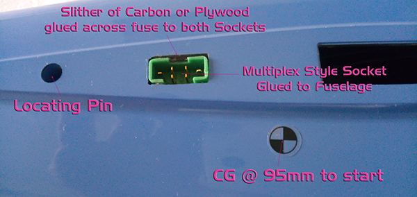
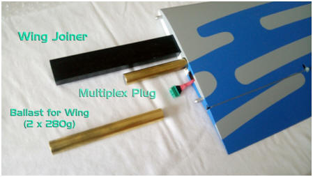
A wiring harness is straightforward for me, as is casting lead in a K&S Brass tube. I used 'Multiplex style plugs and sockets for the wing servos, one half glued in the fuselage with a strip of carbon gluing the two together so they stay in place and will not push inside the fuselage, the other half on a flying lead disappears inside the hollow wings when they are joined. While I shall not put lead ballast in the fuselage I shall use it on odd occasions in the wings. The two pieces here weigh more or less 560g. Do you think a moulded model comes ready to fly, not this one. I needed to do quite a bit to get it how I like it to be. The finished 2 metre model before its maiden flight comes in at just about 2kg. Whether it's better than the Kinetic remains to be seen. |
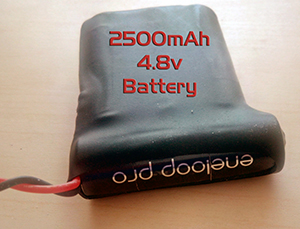
I used 4 Eneloop 2500mAh cells for the power supply and I
also cast a lead nose weight of 130g as suggested in the building
instructions. I then added another 42g to balance. I
glued the shrouds over the clevis exits on the wings and added some
of my own design waterslide transfers the making of which I
described some time ago in the ISA Newsletter, The Beacon.
|
||||||||||||||||||||
|
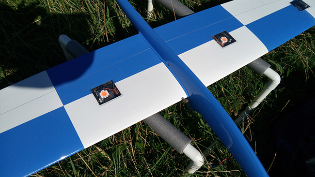
I later added a couple of powerful 10 watt full spectrum LEDs from Banggood.com just for fun, as is my wont. I put them under the clear flap servo covers using the metal servos as heatsinks as these LEDs get very hot even though they are mounted on an aluminium substrate. They glow a very bright pink colour.
This added another 40g. to the flying weight. These LEDs are used for growing 'special plants' indoors and are in fact a matrix of 9 LEDS under some sort of orange silicone filter, they get very hot hence the aluminium heatsink. I run them on a 10% duty cycle so they do not overheat. They are clearly visible at 200m, perhaps even more, in daylight. Specification 9-12V_10W_900mA_800-900Lm_380nm-840nm_View 120º |
|||||||||||||||||||||
|
(If the video above doesn't show on your Windows screen you will have to turn off tracking protection at the top right of the screen. Find the gear cog then click Tools, Safety, Turn off Tracking protection and the refresh the screen, F5.) |
|||||||||||||||||||||


 They are driven by a 3S 270mAh LiPo
pack I made from Nano-Tech cylindrical
cells which is situated in the fuselage ballast tube. The switching
is done by a Turnigy RC switch from HK and the flash rate is determined by
Logic Switch on the OpenTx firmware on my Horus. (0.1 sec. every 10
seconds or 0.1 sec. every 5 seconds)
They are driven by a 3S 270mAh LiPo
pack I made from Nano-Tech cylindrical
cells which is situated in the fuselage ballast tube. The switching
is done by a Turnigy RC switch from HK and the flash rate is determined by
Logic Switch on the OpenTx firmware on my Horus. (0.1 sec. every 10
seconds or 0.1 sec. every 5 seconds)